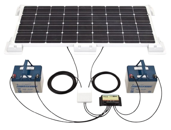
The transition to alternative power sources requires not only the purchase of all the equipment, but also its proper integration into a single network. The efficiency, stability and safety of the entire plant depend directly on how the solar panels are connected. As each module is a direct current generator, its integration requires strict compliance with electrical standards.
Let us take a detailed look at the key rules and diagrams that will help you build an efficient solar power station.
Features of connecting solar panels
Essentially, connecting solar panels involves forming an electrical circuit to transmit energy to the inverter with minimal losses. The physical parameters of the current at the input to the power equipment are entirely determined by the chosen connection configuration. By altering the wiring diagram, engineers control the output voltage and current, adapting the solar array to the technical requirements of a specific inverter.
Incorrect interconnection of solar panels leads to a critical shortfall in energy output or equipment failure due to overvoltage or fire. Therefore, before installation begins, it is essential to accurately calculate the string parameters and ensure flawless protection for each component.
Series connection of solar panels
The series configuration is the most popular option for grid-connected and hybrid systems. The principle is simple: the positive terminal of the first panel is connected to the negative terminal of the second, the positive terminal of the second to the negative terminal of the third, and so on. The free wires at the start and end of this circuit are connected to the inverter. Experts refer to such a circuit as a ‘string’.
The main feature of this configuration is that the voltage of all the panels is added together, whilst the current remains constant. For example, if 10 panels are connected in a single circuit, each producing a voltage of 40 V and a current of 10 A, the output will be:
Voltage = 10 × 40 = 400 V
Current = 10 A
Most inverters have a start-up voltage typically ranging from 120–200 V, so this circuit allows the system to start up quickly. Furthermore, as the current remains low, the installation does not require particularly thick wires, and energy losses in the cables as the electricity travels to the inverter will be minimal.
However, this method of connecting solar panels has one major drawback — it is sensitive to shading. As all the energy flows through a single circuit, the total current of the entire circuit drops to the level of the weakest panel. If a tree or a chimney shades even a single module, the power output of the entire circuit will drop immediately, even if the other nine panels are perfectly exposed to the sun.
Parallel connection of solar panels
The parallel configuration is mainly used in small off-grid systems (at 12, 24 or 48 V) and with simpler PWM controllers. Here, the setup is different: all the positive terminals from all the panels are connected to a single common point, and all the negative terminals to another. Special Y-connectors are used for this purpose.
With this type of connection, the current is increased, whilst the voltage remains the same as that of a single panel. If we take the same 10 modules (each rated at 40 V and 10 A) and connect them in parallel, the output will be:
Voltage = 40 V
Current = 10 × 10 A = 100 A
The main advantage of the parallel configuration is its resistance to shading. If a tree blocks one or two panels, they will simply produce less current, but this will not affect the operation of the neighbouring modules at all. Each panel operates independently.
The main drawback is the enormous current (in our example, 100 amperes). Because of such a powerful current, you have to buy very thick and expensive copper cables; otherwise, the wires will overheat and energy will be lost. Furthermore, a low voltage of 40 V is simply not enough to power a standard grid-tied inverter, which is why a pure parallel connection is rarely used.
Combined (series-parallel) connection
To combine the advantages of both methods and eliminate their disadvantages, a combined configuration is used. It works as follows: first, the panels are connected into several separate series circuits (strings) to increase the voltage, and then these circuits are connected to the inverter in parallel to increase the current and the total power.
Suppose we need to connect 24 panels (each rated at 40 V and 10 A). If we divide them into two strings of 12 panels in series each and connect these strings in parallel, we will obtain the following at the inverter input:
Voltage = 12 × 40 V = 480 V
Current = 2 × 10 A = 20 A
This approach provides an ideal balance: the voltage has risen to a level that is comfortable for the inverter, whilst the current remains moderate. As a result, a standard solar cable with a cross-section of 4 or 6 mm² is suitable for the installation.
Furthermore, the combined configuration copes much better with shading. If a tree shades one panel, the output will drop only in the single circuit where that panel is located. The second circuit, situated on the other part of the roof, will continue to operate at full capacity.
Choosing the optimal connection configuration
The decision on which specific connection method to use for the solar panels must be made at the design stage, based on the inverter’s technical specifications. Its internal technical limitations dictate the configuration rules for the entire array.
The first parameter is the maximum DC input voltage. When engineers calculate the number of panels in a circuit, they look at the open-circuit voltage and must take winter frosts into account. The fact is that in cold weather, silicon panels produce a significantly higher voltage than in summer. If the total circuit voltage on a frosty day exceeds the inverter’s limit by even a few volts, it will burn out instantly.
The second parameter is the operating voltage range of the MPPT tracker and the maximum input current. Here, the situation is the opposite — on hot summer days, the voltage of the panels drops. It must not fall below the inverter’s minimum threshold, otherwise it will simply switch off. At the same time, the current from parallel circuits must not exceed the inverter’s permissible limit, so that the equipment does not clip the excess energy generated.
Safety when connecting solar panels
A solar power station is a high-power electrical installation. The specific nature of photovoltaic modules is that they cannot be switched off at the push of a button: as soon as light hits the silicon, it generates voltage. Working with high-voltage direct current is more dangerous than working with a 220 V alternating current mains supply, as a direct current circuit break creates a stable electric arc that is extremely difficult to extinguish.
Selecting suitable cables and connectors
It is strictly forbidden to use domestic cables such as PVS or SHVVP for constructing DC lines. A special solar cable, marked PV1-F or H1Z2Z2-K, has been developed for renewable energy applications. Its design takes into account harsh operating conditions:
Double insulation: the cross-linked polymer layers are non-flammable and do not emit toxic gases when heated.
UV resistance: the sheath is designed to withstand 25 years of exposure to direct sunlight and does not crack due to ozone or precipitation.
Temperature range: the cable retains its properties at temperatures ranging from -40°C to +90°C.
Conductor material: multi-strand tinned copper is used, which effectively resists corrosion in humid environments.
MC4-standard sealed connectors with an IP67/IP68 protection rating are used to connect the panels. All contacts must be crimped using a specialised crimping tool — any twisted connections secured with insulating tape are strictly prohibited.
Overload and short-circuit protection
Before being connected to the inverter, each string must pass through a DC protection panel (DCP). It contains the following components:
Fuse links (gPV): fast-acting DC fuses that protect circuits from reverse currents in the event of an internal short circuit in one of the strings.
SPV (Surge Protection Device): this module diverts induced ultra-high-voltage surge currents (from nearby lightning strikes) via the earthing circuit to earth, thereby protecting the inverter circuit board.
DC disconnector: a specialised switch with arc-suppression chambers, optimised for safely breaking the DC circuit under load during maintenance work.
It is therefore advisable to entrust such work to professionals. Only precise engineering calculations, high-quality certified cables and reliable protective automation can guarantee that your station will operate efficiently and safely for decades to come.
 0800 30 13 77
 0800 30 13 77
 En
En







Відгуків немає, поки що.